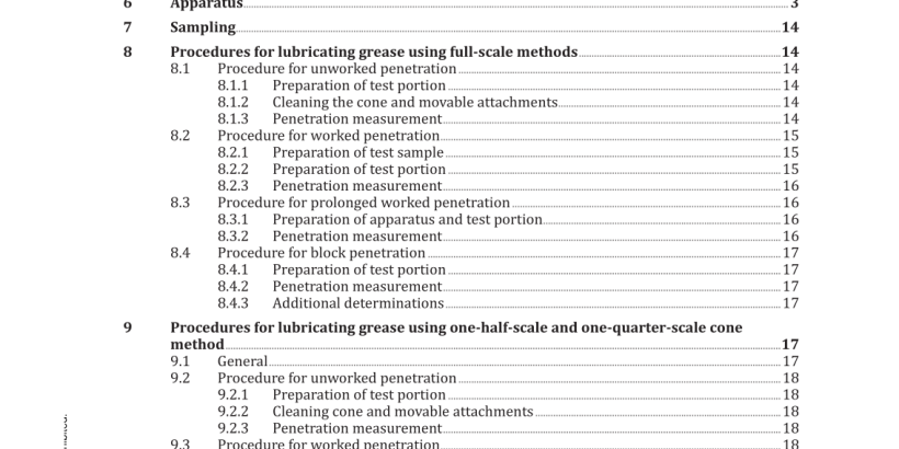
ISO 2137:2020 pdf download – Petrol eum products and lubricants – Determination of cone penetration of lubricating greases and petrolatum.
5? Classifications,? procedures? and? limitation The National Lubricating Grease Institute (NLGI) classifies greases according to their consistency, as measured by the 60 strokes worked penetration. The NLGI classification includes nine consistency numbers or grades, each grade corresponding to a given range of worked penetration. The NLGI classification is given in ISO 6743-99 and ISO 12924. Clause 8 specifies four procedures for determining the consistency of lubricating greases by measuring the penetration of a full-scale cone. These procedures cover the measurement of unworked, worked, prolonged worked and block penetrations. Penetrations up to 500 units can be measured. Clause 9 specifies methods for determining the consistency of lubricating greases when only small samples are available, by the use of cones a one-half-scale or one-quarter-scale of that used in Clause 8. The methods are applicable to greases having penetrations of 175 units to 385 units with the full-scale cone and are intended for use only if the size of the test sample prevents the use of cones described in Clause 8. They are not intended to replace the full-scale penetration as described in Clause 8, although a conversion to full-scale penetration is given in 10.2. See 9.1 for the limitations on the use of one-quarter- scale cones due to the poor precision. NOTE 1 Unworked penetrations do not generally represent the consistency of greases in use as effectively as do worked penetrations. The latter are usually preferred for inspecting lubricating greases. NOTE 2 Penetration of block greases can be obtained on those products that are sufficiently hard to hold their shape. These greases generally have penetrations below 85 units.
6.2 Cones 6.2.1 Full-scale cone, consisting of a conical body of magnesium or other suitable material with a detachable, hardened steel tip. Dimensions and tolerances shall be as shown in Figure 2. The total mass of the cone shall be 102,50 g ± 0,05 g and the total mass of its movable attachments shall be 47,50 g ± 0,05 g. The attachments consist of a rigid shaft having a stop at its upper end and a suitable means at its lower end for engaging the cone. The interior construction may be modified to achieve the specified mass, provided that the general contour and mass distribution are not altered. The outer surface shall be polished to a very smooth finish. For penetrations up to 400 units, the optional cone as shown in Figure 3 may be used. For this cone the total mass shall be 102,50 g ± 0,05 g, and the total mass of movable attachments shall be 47,50 g ± 0,05 g. 6.2.2 One-half-scale cone and shaft, made of steel, stainless steel or brass with a hardened steel tip of 45 Rockwell C hardness to 50 Rockwell C hardness and constructed to conform to the dimensions and tolerances shown in Figure 4. The shaft may be made of stainless steel. The total mass of the cone and its movable attachments shall be 37,50 g ± 0,05 g. The mass of the cone shall be 22,500 g ± 0,025 g. The mass of the movable attachments shall be 15,000 g ± 0,025 g. 6.2.3 One-quarter-scale cone and shaft, consisting of a conical body of plastics or other low-density material with a hardened steel tip of 45 Rockwell C hardness to 50 Rockwell C hardness, and constructed to conform to the dimensions and tolerances shown in Figure 5. The shaft may be constructed of magnesium alloy. The total mass of the cone and its movable attachments shall be 9,380 g ± 0,025 g. The total mass of the cone and its movable attachments may be adjusted by adding small a shot to the cavity of the shaft.
6.3 Grease workers 6.3.1 Full-scale grease worker, conforming to the dimensions shown in Figure 6. The sizes of non-dimensioned parts are not critical and may be varied according to individual requirements. Other methods of fastening the cover and securing the worker may be used. The grease worker may be constructed for either manual or mechanical operation. The design shall be such that a rate of 60 strokes per minute ± 10 strokes per minute, with a minimum length of 63 mm, can be maintained. A suitable thermometer, standardized at 25 °C, shall be provided for insertion through the vent valve. 6.3.2 One-half-scale grease worker, conforming to the dimensions given in Figure 7, of stainless steel and with a capacity of 50 ml. Other methods of fastening the cover and securing the worker may be used. The worker may be constructed for either manual or mechanical operation. The design shall be such that a rate of 60 strokes per minute ± 10 strokes per minute, with a minimum length of 35 mm, can be maintained. 6.3.3 One-quarter-scale grease worker, made of stainless steel and conforming to the dimensions given in Figure 8. Other methods of fastening the cover and securing the worker may be used. The worker may be constructed for either manual or mechanical operation. The design shall be such that a rate of 60 strokes per minute ± 10 strokes per minute, with a minimum length of 14 mm, can be maintained.
