ISO 18543:2021 pdf download – Glass in building — Electrochromic glazings — Accelerated ageing test and requirements.
1 Scope This document specifies the accelerated ageing test and requirements for electrochromic glazings intended to either control direct or indirect solar transmission, or both. The electrochromic glazings can be assembled as insulating glass unit, laminated glass or combination of both. The test method described in this document is only applicable to chromogenic glazings that can be switched between different transmission states using an electrical stimulus. This test method is not applicable to other chromogenic glazings such as photochromic and thermochromic glazings, which do not respond to electrical stimulus. This test method is applicable to any electrochromic glazing fabricated for use in buildings such as in doors, windows, skylights, exterior wall systems and glazing exposed to solar radiation. The materials used for constructing the electrochromic glazing and for electrochromically changing its optical properties can be inorganic or organic materials.
2 Normative references The following documents are referred to in the text in such a way that some or all of their content constitutes requirements of this document. For dated references, only the edition cited applies. For undated references, the latest edition of the referenced document (including any amendments) applies. ISO 9050, Glass in building — Determination of light transmittance, solar direct transmittance, total solar energy transmittance, ultraviolet transmittance and related glazing factors ISO 12543 (all parts), Glass in building — Laminated glass and laminated safety glass ISO 20492 (all parts), Glass in buildings — Insulating glass
The procedure consists of the following steps: — step 1: initial characterization of the test sample and determination of the cycling conditions: — light transmittance at highest (τ H,i ) and at lowest (τ L,i ) transmission states, at room temperature; — switching time from highest to lowest transmission states (t L,i ) and reverse (t H,i ), at room temperature; — switching time of 85 % of the dynamic range in both directions, at the selected test temperature; — calculation of the total switching cycle to be used in step 2; — step 2: cycling and radiation exposure of the test sample in a chamber maintained at the selected test temperature; — step 3: final characterization of the test sample: — light transmittance at highest (τ H,f ) and at lowest (τ L,f ) transmission states, at room temperature; — switching time from highest to lowest transmission states (t L,f ) and reverse (t H,f ), at room temperature. When compared to the initial characteristics, the final characteristics shall meet the requirements given in Clause 9.
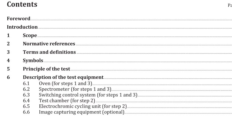
6 Description of the test equipment 6.1 Oven (for steps 1 and 3) An oven shall be used to carry out optical measurements and to define the switching cycle of the electrochromic glazings at the requested temperatures. It shall be large enough for the largest electrochromic glazing to be tested and shall be able to reach the electrochromic glazing testing temperature. The oven shall also be designed to permit using the equipment described in 6.2 and 6.3 for optical measurements while the electrochromic glazing shall be maintained at the temperature chosen for step 2. Thermocouples shall be used to measure specimen temperature in the oven.
6.2 Spectrometer (for steps 1 and 3) A spectrometer shall be used for obtaining and storing data from the optical characterization in the range 380 nm to 780 nm of the specimens in the highest and lowest transmission states. The lamp source can be a tungsten lamp or other lamp source that provides illumination from 380 nm to 780 nm. Fibre optic cables extend from the lamp source into the electrochromic glazing specimen holder and from the electrochromic glazing specimen holder to the spectrometer. One optical fibre guides the incident light from the lamp source to one side of the specimen; another optical fibre guides the transmitted light to the spectrometer attached to a computer. The fibres shall be optically coupled by properly aligned collimating lens assemblies attached to both the illuminating and the collecting fibres. 6.3 Switching control system (for steps 1 and 3) The switching to and from highest and lowest transmission states during spectrophotometer transmittance measurements can be done by means of a computer-controlled multichannel potentiostat or by manufacturer-supplied control system. 6.4 Test chamber (for step 2) The test chamber shall be temperature-controlled and shall contain lamps that have been filtered appropriately in order to simulate the spectral power distribution of solar radiation over the ultraviolet, visible and near infrared wavelength regions. As an example, Figure 2 shows the spectral irradiance of an appropriately filtered xenon arc source compared to the global Air Mass 1,5 spectrum.
